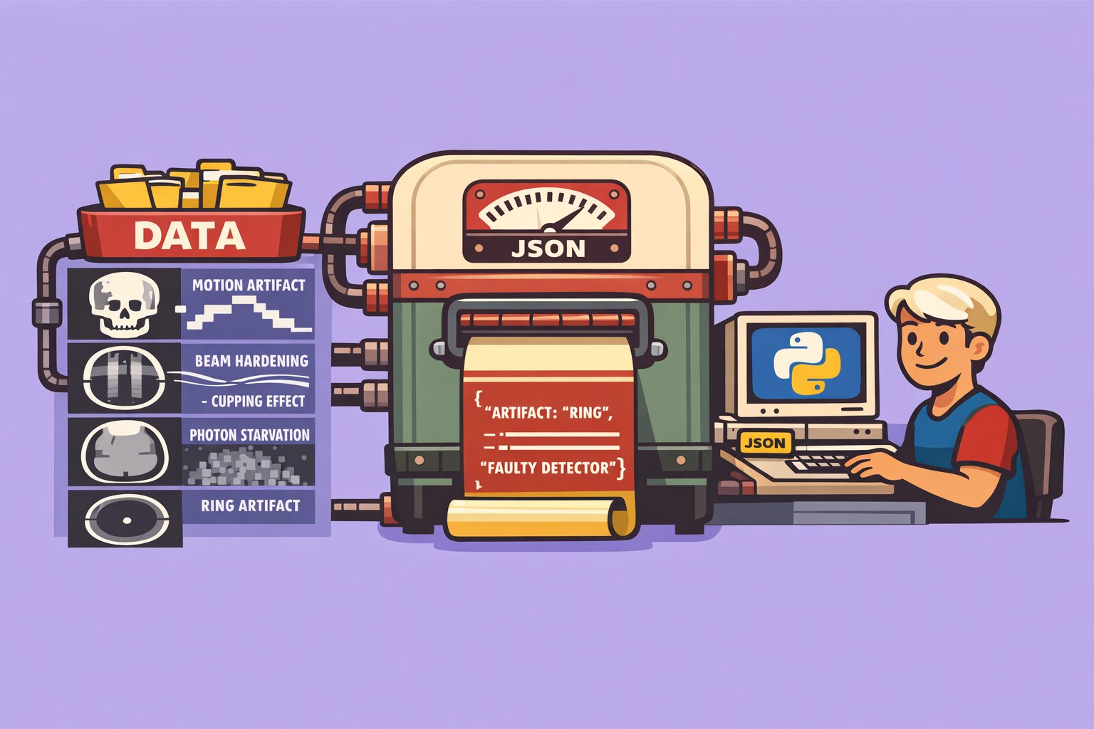
Computed Tomography (CT) scans are invaluable tools in modern medicine, providing detailed cross-sectional images of the body. However, the clarity and diagnostic utility of these images can often be compromised by various artifacts. Understanding these artifacts—their causes and how to mitigate them—is crucial for both medical professionals and anyone interested in diagnostic imaging.
CT artifacts can generally be categorized into three main groups: patient-based, physics-based, and hardware-based. While these categories often intertwine, classifying them helps in understanding their root causes and appropriate solutions.
Patient-Based Artifacts
These artifacts arise from the patient’s physiological state or presence during the scan.
1. Motion Artifact
Motion artifact occurs when a patient moves during image acquisition, leading to misregistration of anatomical structures. This can manifest as:
- Step appearance: A distinct interruption or “step” in the contour of an organ or bone.
- Streaking: Linear artifacts across the image.
- Misregistration: Anatomy appearing in incorrect locations or duplicated.
Causes: Patient breathing, swallowing, involuntary movements (e.g., heart beating), or speaking.
How to mitigate:
- Clear Communication: Thoroughly explain the procedure to the patient and instruct them to remain still and hold their breath if required.
- Immobilization: Use padded restraints, head holders, or foam molds, especially for pediatric or uncooperative patients. Sedation may be considered if necessary.
- Faster Scan Protocols:
- Increase rotation speed of the X-ray tube.
- Increase table speed (higher pitch).
- Decrease the scan coverage (smaller area).
- Utilize helical scanning, which provides continuous data acquisition, reducing opportunities for motion compared to step-and-shoot axial scanning.
- ECG Gating: For cardiac imaging, acquire data only during specific phases of the cardiac cycle, either prospectively (triggering acquisition) or retrospectively (selecting data after acquisition). This minimizes motion blur from heart movement.
2. Transient Interruption of Contrast
This artifact, frequently observed in CT Pulmonary Angiography (CTPA), occurs when there’s an unexpected dilution of contrast in specific vessels, mimicking a blockage.
Causes:
- Deep Breath: A deep inspiration can drastically decrease intrathoracic pressure, increasing venous return of uncontrasted blood from the inferior vena cava, diluting the contrast in the pulmonary arteries.
- Pregnancy: Increased intra-abdominal pressure in pregnant patients can lead to similar effects.
How to mitigate: Optimize contrast injection protocols, potentially by adjusting the timing of acquisition or the volume/flow rate of contrast, and by instructing the patient on proper breathing techniques.
Physics-Based Artifacts
These stem from the physical principles of X-ray attenuation and image reconstruction.
1. Beam Hardening Artifact
This artifact arises because X-ray beams are polychromatic (composed of various energy levels), and lower-energy X-rays are preferentially attenuated as the beam passes through tissue. This “hardens” the beam, increasing its average energy. CT reconstruction algorithms, however, assume a monochromatic beam and constant linear attenuation coefficients, leading to errors.
Manifestations:
- Cupping Artifact: A “cupping” appearance where the center of a uniform object appears darker (lower Hounsfield Units) than its periphery. This occurs because the central part of the beam, having traversed more tissue, is harder than the peripheral parts.
- Dark Streaks: Dark bands appearing between two dense structures (e.g., petrous bones, metal implants). The beam passing between these structures is excessively hardened, leading to lower-than-actual attenuation values in the intervening tissue.
How to mitigate:
- Increase X-ray Tube Voltage (kVp): A higher kVp produces a higher average energy beam, reducing the relative change in beam hardening.
- Iterative Reconstruction Algorithms: These advanced algorithms do not rely on the false assumptions of traditional filtered back-projection, leading to significantly reduced beam hardening artifacts.
- Filtration:
- Pre-hardening: Use metal filters (e.g., aluminum, copper) to remove low-energy photons before they reach the patient, reducing their contribution to dose without significantly impacting image quality.
- Beam Shaping Filters (Bowtie Filters): These filters preferentially attenuate X-rays at the periphery of the beam (corresponding to the thinner parts of the patient), helping to flatten the beam profile and reduce cupping centrally.
- Dual-Energy CT (DECT): Acquire data at two different X-ray energy levels. This allows for the creation of “virtual mono-energetic” images, which effectively simulate scanning with a single X-ray energy, virtually eliminating beam hardening.
- Correction Algorithms: Apply post-processing algorithms that normalize Hounsfield unit values based on scanner calibration and patient anatomy.
2. Photon Starvation Artifact
This artifact occurs when an insufficient number of X-ray photons reach the detectors, typically due to excessive attenuation by the patient or dense structures. This leads to a noisy image with poor contrast.
Manifestations:
- Streaky Noise: The image exhibits characteristic streaky or “grainy” noise.
- Low Contrast: Difficulty in distinguishing between different tissues.
- High Hounsfield Units at Periphery: In severe cases, the image may show erroneously high Hounsfield units at the edges of a very dense object.
Causes:
- Large Patients: X-rays traverse more tissue, leading to high attenuation.
- Very Dense Structures: Bone, metal implants, or contrast agents can absorb a large proportion of X-rays.
How to mitigate:
- Increase X-ray Tube Output: Increase kVp (to make the beam more penetrating) or mA (to increase the number of photons).
- Iterative Reconstruction: More effectively handles noise and can produce diagnostic quality images with fewer photons.
- Reduce Pitch: For helical scans, reducing the pitch (below 1) causes overlapping slices, effectively increasing the number of photons detected per anatomical region and improving signal-to-noise ratio.
- Automatic Tube Current Modulation (ATCM): This technology adjusts the tube current (mA) dynamically based on patient attenuation. It increases mA when X-rays pass through denser or wider body parts (e.g., shoulders, pelvis), ensuring adequate photon flux to the detectors.
- Adaptive Filtering: Smooths out regions with critically low photon counts (below a predefined threshold), reducing localized noise propagation in back-projection.
- Metal Artifact Reduction (MAR) Algorithms: Specialized algorithms designed to reduce artifacts caused by metallic implants, which can induce severe photon starvation and beam hardening. Note that these algorithms can sometimes introduce new artifacts.
3. Partial Volume Artifact
This artifact occurs when a single voxel contains two or more tissues with significantly different attenuation coefficients. The CT number assigned to that voxel will be an average of the attenuation values of all tissues within it, leading to blurring or misrepresentation of small structures.
Manifestations:
- Blurring: Edges of small, distinct structures appear blurry.
- False Representation: Small structures may appear larger or smaller than their actual size, or their CT numbers may be inaccurate.
How to mitigate:
- Reduce Slice Thickness: Thinner slices mean smaller voxels in the Z-axis, reducing the likelihood of multiple tissues occupying a single voxel in that dimension. This is achieved by adjusting collimation or detector binning.
- Higher Spatial Resolution: While primarily related to slice thickness, improving in-plane resolution (X-Y plane) further minimizes partial volume effects by making pixels smaller.
Hardware-Based Artifacts
These artifacts are due to malfunctions or limitations of the CT scanner components.
Ring Artifact
This distinctive artifact appears as a circular or spiral pattern in the image.
Causes: A faulty or miscalibrated detector element in a third-generation CT scanner (where detectors rotate with the X-ray tube). If a detector consistently produces incorrect or no signal, all projection data acquired by that detector are flawed, resulting in a ring in the reconstructed image.
Manifestations: A bright or dark ring, or a series of concentric rings, centered on the isocenter of the scan. In helical scans, this manifests as a spiral artifact.
How to mitigate:
- Detector Recalibration/Replacement: The faulty detector needs to be recalibrated or replaced by a service engineer.
- Scanner Generation: Fourth-generation CT scanners, with their stationary ring of detectors, are inherently immune to ring artifacts (though they can have other detector-related issues).
- Image Interpretation: Recognizing a ring artifact is crucial to avoid misinterpreting it as pathology, especially if it does not obscure critical anatomical details.
Understanding these common CT artifacts is fundamental for producing high-quality diagnostic images and avoiding misinterpretations. By implementing appropriate mitigation strategies and leveraging advanced imaging techniques, we can ensure that CT scans continue to provide accurate and reliable information for patient care.
🔍 Discover Kaptan Data Solutions — your partner for medical-physics data science & QA!
We're a French startup dedicated to building innovative web applications for medical physics, and quality assurance (QA).
Our mission: provide hospitals, cancer centers and dosimetry labs with powerful, intuitive and compliant tools that streamline beam-data acquisition, analysis and reporting.
🌐 Explore all our medical-physics services and tech updates
💻 Test our ready-to-use QA dashboards online
Our expertise covers:
🔬 Patient-specific dosimetry and image QA (EPID, portal dosimetry)
📈 Statistical Process Control (SPC) & anomaly detection for beam data
🤖 Automated QA workflows with n8n + AI agents (predictive maintenance)
📑 DICOM-RT / HL7 compliant reporting and audit trails
Leveraging advanced Python analytics and n8n orchestration, we help physicists automate routine QA, detect drifts early and generate regulatory-ready PDFs in one click.
Ready to boost treatment quality and uptime? Let’s discuss your linac challenges and design a tailor-made solution!
Get in touch to discuss your specific requirements and discover how our tailor-made solutions can help you unlock the value of your data, make informed decisions, and boost operational performance!
Comments